Etherwave Standard & Plus (EWS & EW+) Theremin Modifications
Contents: | |||
Chapter 1. | Etherwave Standard (EWS) Theremin Modifications | ||
Chapter 2. | Etherwave Standard Theremin simplest ever ‘Lower-Register’ Modification | ||
Chapter 3. | Etherwave Standard Theremin ‘Rockmore-Sound’ Modification | ||
Chapter 3.1 | Theremin Sound Spectrum | ||
Chapter 3.2 | Modified EW Standard Circuit Descriptions | ||
Chapter 4. | EW Standard and EW+ Theremin Modification (EW-REB 12-2020) | ||
Chapter 4.1 | EW S/+ Theremin Rockmorizer Extension Board | ||
Chapter 4.2 | Audio Pulse-Width / Duty-Cycle and Sound-Spectrum (EW-REB 12-2020) | ||
Chapter 4.3 | Audio Volume-Control Dynamic Extension | ||
Chapter 4.4 | EW Standard and EW+ Theremin Modification Circuit Descriptions | ||
Chapter 4.5 | EW 12-2020 Extension Board Variants | ||
Chapter 4.6 | Modified EW S/+ Main-Board (EW-REB 12-2020) | ||
Chapter 4.7 | Modified EW+ Front-Panel with Mute-Switch & Indicator-LED | ||
Chapter 5. | EW Standard and EW+ Theremin Modification | ||
Chapter 5.1 | Active (AF) Detector Low-Pass-Filter | ||
Chapter 5.2 | Pitch dependent Duty-Cycle and Pulse-Ratio Characteristics | ||
Chapter 5.3 | Volume dependent Pitch Duty-Cycle and Pulse-Ratio Characteristics | ||
Chapter 5.4 | Analog 440Hz ‘A4’ Pitch-Indicator | ||
Chapter 5.5 | Schematics of the EW-REB 01-2021 Extension Board | ||
Chapter 5.6 | EW Standard and EW+ Theremin Modification Circuit Descriptions | ||
Chapter 5.7 | Prototype of the | ||
Chapter 5.8 | EW-REB 01-2021 Volume Response | ||
Chapter 6. | EW Standard and EW+ Theremin Modification | ||
Chapter 6.1 | EW Standard and EW+ Theremin Modification Circuit Descriptions | ||
Chapter 6.2 | Pitch Linearity Measurements | ||
Chapter 6.3 | EW-REB 08-2021 Extension Board | ||
Chapter 7. | Preparation of Adjustment-Holes below the Oscillator-Coil-Cans at EW Main-Board | ||
Chapter 8. | Modified EW Standard Front-Panel, Additional Controls, Power- and Audio Jacks | ||
Chapter 9. | Modified Trumpet Traveling Case for EW Standard | ||
1. Etherwave Standard (EWS) Theremin Modifications
In the course of my theremin research, I bought a Moog Etherwave Standard (EWS) Theremin (Etherwave is registered trade mark of Moog Music Inc. 554C Riverside Drive, Asheville, NC 28801 [69]) to compare the performance to my home build Theremin prototypes. Because the sound and the volume control response of the EWS did not satisfy my sound expectations, I decided to modify the circuit according to the findings of my Theremin research. The first result is presented in the video below.
1.1 Introduction
The EWS Theremin is the most popular Theremin instrument. It holds many deficiencies. These are the awkward sound, the unfavorable volume response, the missing mute switch and the cable jacks at the front and back of the instrument. In addition, a suitable traveling case (which perfectly holds the unfastened antennas) is missing.
Several attempts have been made to overcome these issues, only few seem to be simple enough to be build in subsequently.
Nevertheless, without the unresting work of Robert Moog and this EWS instrument, designed by him, the Theremin probably would be forgotten already long ago.
It is possible to implement a simplified (rectangular) audio-shape, which is quite close to the Rockmore instrument sound, using the already existing components of the EWS and adding a few additional parts, as described at ‘EWS Theremin Rockmore-Sound Modification’ and the improved 'EW Standard and EW+ Theremin Modifications' below.
After implementing the proposed modifications, the ‘Brightness’ knob (controlling the slope of the audio signal) usually has to stay fully clockwise and the ‘Waveform’ knob (affecting the width of the rectangular audio pulse) can be slightly adjusted for more or less formant spectral distribution.
To provide even more brightness of sound, R24 can be made adjustable by a series trimmer of 25kOhm to fine adjust the flanks of the rectangular pulse and the pulse width (not shown in the schematics).
It must be emphasized, that when implementing the proposed modifications, the original EWS sound cannot be retrieved by simply re-adjusting ‘Waveform’ or ‘Brightness’; nevertheless, a quite similar tone of poor quality may be achieved.
To expand the lower register of the EWS (bass modification), a very simple solution has been found as described below.
2. Etherwave Standard Theremin simplest ever ‘Lower-Register’ Modification (21.05.2020)
For those who only like to expand the lower register, preserving the EWS sound and circuit, a very simple solution has been found. The 'EW Theremin bass modification' only applies a trimmer capacitor of 1pF to 4pF and a 150kOhm standard resistor as described in the Etherwave Standard Theremin simplest ever lower-register modification test video below.
At the EWS circuit, the pitch oscillators are connected by the 15pF capacitors C2 and C6 to the anode of diode D4. Inherent to this construction is the introduced coupling from one oscillator to the other via the series connection of C2 and C6. The value of the capacitors is quite low, but there’s enough RF transferred between the oscillators which shortens the lower register of the instrument. To reduce the coupling between the oscillators, the proposed circuit forms a sort of Bridged-T Notch-Filter, which introduces higher damping and phase shift. A trimmer capacitor of 1pF to 4pF (Cx) and a 150kOhm (Rx) standard resistor are connected in series. The capacitor can be of the variable ceramic or plastic type or constructed by two twisted isolated solid wires as shown in the pictures (the capacitance depends mainly on the used wires; values given are exemplary). The typical value is 2.5pF. The capacitor/resistor combination has to be soldered to C2 and C6 at the oscillator side. The capacitor has to be adjusted for the desired bass sound and optimal pitch spacing; it may be necessary to re-adjust the oscillator coils.
 |  |   |
The Pitch-Oscillator/AF-Detector simulation picture shows the schematic and the resulting detected audio-wave at approx. 100Hz for different values of the additional adjustable capacitor (C8: 0p5/1p5/2p5/3p5). With rising value, the waveform gets more and more symmetrical (tilt moves from left to middle of the wave; in the practical circuit implemented to the EWS, the wave tilt can actually be shifted from left to right).
")
EW Standard Theremin: Lower Register Modification Simulation 100Hz (various compensation capacitor settings)
The next pictures show the uncompensated and compensated waveform at 100Hz and the compensated signal at 50Hz.
")
EW Standard Theremin: Lower Register Modification Simulation 100Hz (no compensation)

EW Standard Theremin: Lower Register Modification Simulation 50Hz (compensation)

EW Standard Theremin: Lower Register Modification Simulation 100Hz (compensation)
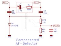
To describe the function principle of the modified Bridged-T-Filter, the following simplified simulation has been set up. For simplification, only resistors and capacitors have been used, omitting the detector-diode. R1 and R2 are the assumed oscillator ‘output’ impedances, R8 represents the simplified impedance of detector-diode paralleled by the AF voltage divider/LPF. C5 and R10 are the added components of the ‘compensation’ circuit. The oscillator voltage represented by V1 with ‘output’ impedance R1 (RF-C) is coupled to the ‘output’ impedance R2 (RF-V) of the second oscillator (no voltage source shown for simplification) via the Bridged-T components. The Bode-Plot shows the damping- and phase shifting action of this notch-filter configuration. The damping (and the dependent phase) can be adjusted by C5. Rising values of C5 increase the damping up to 6dB (1nF). R10 sets the center frequency which is quite independent of the damping, defined by C5. For use in the EWS instrument, the value of C5 is typically 2.5pF. This already produces sufficient damping and phase-shift for extending the lower-register. The changed circuit has very little effect to the detector’s audio-signal output.

Etherwave Standard Theremin: Bridged-T-Notch-Filter Simulation
Note: Years after implementing this modification to the EWS Theremin, I found out that a somewhat similar circuit was already described by L.D. Korolyov [70] (L.D. Korolyov ‘Modern theremin’, Radio 1985 No. 2 & 1985 No. 3 / Л. Д. Королёв ‘Современный терменвокс’ Радио, №2 1985г и №3 1985г). The conversion of the detected audio signal to rectangular pulses and the application of formant filter techniques for creation of timbres is also described within the articles. It is not known if the pulse width changed as described above while varying the pitch to create a pleasing sound over the whole range. It must be emphasized, that the work of Korolyov was focused on creating an easy to play Theremin inspired instrument, providing a wide range of selectable timbres. The descriptions published at aetherwellen-musik.de focus on recreating a sound close to C. Rockmore’s instrument – not on achieving many timbres to compete with synthesizers.
3. Etherwave Standard Theremin ‘Rockmore-Sound’ Modification
(RS-Mod.) (20.09.2023)
At the schematics, the proposed modifications are marked by dotted boxes in red color. 'NC' (not connected) indicates non-populated components, 'TB' components define PCB tracks to be cut for disconnection.
Note: The signal VCA-OUT is supplied by connector J4-4 (U3D-9), the branch indicator is missing in the schematics below (rev. o.3).

The schematics represent the updated version of the EW Standard PCB, which differs from those models produced earlier [67], [68].

Note: At revision 0.3 (2022-04-23), the pinning of U1 (78L12) was corrected as well as the designator of R11. The denotation 'Varaible Volume Oscillator' has to be changed to 'Fixed Volume Oscillator'.
 | EW Standard Theremin Modification Schematic BW 0v3 RS-Mod. EW Standard Theremin Modification Schematic BW 0v3 EW-MOD_05-2020_SCH-BW_0v3.pdf (164.36KB) |
RS-Mod. EW Standard Theremin Modification Schematic BW 0v3
| EW-MOD_05-2020_SCH-BW_0v3.pdf (164.36KB) |
3.1 Theremin Sound Spectrum
The objective sound spectrum of a Theremin instrument consists of the lower-, mid- and high-pitch segment. The most noticeable (and simple to describe) partial spectrum is the mid-pitch segment. The spectral lines around the frequency of 220Hz are at the Theremin instrument of Clara Rockmore arranged in groups as follows:
a) fundamental (220Hz), 2nd, 3rd harmonics almost of equal amplitude
b) 4th harmonic nearly completely suppressed (volume dependent)
c) 5th, 6th, 7th harmonics almost equal of amplitude but lower than at a)
d) 8th harmonic nearly completely suppressed (volume dependent)
e) the spectral line sequence (3 lines -1 suppressed -3 lines) repeats with declining amplitudes
It must be mentioned, that the audio pulse-width and thus the sound spectrum is volume dependent. With rising volume (especially at very large volume) the suppression of the 4th, 8th and additional harmonics is reduced. This leads to an extended volume impression. This is comparable to the differentiation of whispering and shouting. Even if a whispering sound is amplified and reproduced with much higher volume, it can be still be recognized as a whisper.
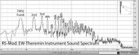
The sound spectrum of the proposed EW Standard Theremin modification (Rockmore-Sound-Modification: RS-Mod.) is shown below. It is quite similar to the timbre of the instrument of C. Rockmore (spectrum taken from the audio of the video ‘Clara Rockmore: The Greatest Theremin Virtuosa‘ by R. Moog 1976), located on the right for comparison; refer to:‘General Functionality of the Rockmore- and Rosen Theremin Instruments according to Leon Theremin’s Design’
 | ") |
RS-Mod. EWS Theremin | Rockmore Theremin |
 | ") |
RS-Mod. EWS Theremin | Rockmore Theremin |
3.2 Modified EW Standard Circuit Descriptions (RS-Mod.)
3.2.1 Modified EW Standard Front-Panel Circuit (RS-Mod.) (25.09.2022)
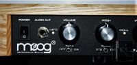
The Front-Panel Circuit consists of the Power-Switch, the Indicator-LED, the Audio-Output Jack, the Mute-Switch and the Potentiometers for Volume, Pitch, Waveform and Brightness control.

The 14V AC voltage of the EWS line wall wart, connected to jack AC-IN is routed to the Power-Switch S1 and back to the power-supply circuit (AC-OUT) via the front-panel connectors J2/J3. The Audio-Output signal AUDIO-OUT is present at jack J1, which is supplied by the AF-Limiter VCA circuit via connectors J2/J3. The Volume-Potentiometer controls the amount of negative VOLUME control-voltage supplied to the AF-Limiter VCA circuit. The Pitch-Potentiometer controls the amount of negative pitch-tuning PITCH voltage, routed to the pitch-tuning circuit. The Waveform-Potentiometer controls the amount of negative WAVE voltage, routed to the AF-Limiter VCA circuit, determining the audio-signal pulse-width. The Brightness Potentiometer’s output voltage BRIGHT is also routed to the AF-Limiter VCA circuit, determining the rise- and fall time of the limited audio-signal. The additional resistors R201 and R202 reduce the BRIGHT control-voltage range to the appropriate level. The DC control-voltages VOLUME, PITCH, WAVE and BRIGHT as well as the +-12V supply voltage and ground are routed to the dedicated circuits via connectors J2 and J3.

The Mute-Circuit at the front-panel consists of the Mute Switch S2 (DPDT – Double Pole Double Throw: closes in the up or down position corresponding to On-On configuration), the connector J4/J5, the bi-color Indicator LED D100 and the accompanying resistors R204 and R203. The values of the resistors are chosen to give equal brightness of the red and green LED (R203 and R204 shall have values of 1.5k to 3k3; the 10k value is a copy-paste failure). One section of S2 connects the +12V supply-voltage to the red (mute) or green (play) indicator LED portion. The other switch shunts the VDET signal to ground (GND) when the instrument is muted. The VDET signal is generated by the Volume-Detector circuit.
3.2.2 Modified EW Standard Volume Control RF-Circuit (RS-Mod.) (20.09.2023)

The modified EWS Volume-Control RF-Circuit consists of the Fixed Volume Oscillator (schematic denotation has to be changed), consisting of Q6, Q7 and the surrounding components with accompanying Volume Tuning Stage, controlled by the VOLUME voltage which is derived from the dedicated potentiometer located at the front-panel, build around Q8. The Volume Antenna Resonator/Detector unit is directly connected to the base of Q7. The value of C27 is reduced to 10nF for increasing detector signal rise-time and the cathode of detector diode D1 is connected to a tap of L7 for improved volume response. The detector circuit generates the volume-control voltage VDET, which can be shorted to ground with Mute-Switch S2, located at the front-panel, in ‘Mute’ position. VDET is directly routed to the Volume Control Amplifier.
3.2.3 Modified EW Standard Volume Control LF-Circuit (RS-Mod.) (12.09.2022)
The modified EWS Volume-Control LF-Circuit consists of the Volume Control Amplifier, the Volume Control Overshoot Low-Pass-Filter (LPF) and the AF-Limiter Voltage-Controlled-Amplifier (VCA).

The Volume Control Amplifier U3C amplifies the VDET signal of the Volume-Detector in a non-linear fashion, due to the feedback of D5 via R37. A negative offset voltage is provided to the amplifier by the divider formed by R101 and R100. C100 serves for offset voltage decoupling. To add this modification, pin 14 of U3C has to be disconnected from ground, e.g. by cutting the PCB track (TB1). The generated volume-control voltage (CTRL-OUT) is supplied to the Volume Control Overshoot Low-Pass-Filter (LPF) via connectors J4/J5. This filter applies the Darlington transistor (U3D) integrated in U3 and the accompanying components which are assembled at an additional PCB. The amount of over- and undershoot, which defines the dynamic volume response e.g. when playing staccato, can be adjusted by trimmer R110. Values are chosen to give appropriate delay, rise/fall time and over/undershoot.
In Leon Theremin’s original design of e.g. the Rockmore instrument, the over/undershoot is mainly defined by the bandwidth of the volume-control detector resonator-tank, which produces ringing at fast frequency changes, causing voltage variations of the resonator and thus the detector tube’s output. This resonator-tank is missing in Robert Moog’s EWS design.
The LPF output signal at pin 4 of J4/J5 is supplied via the divider formed by R103 and R29 to the VCA stage (VCA-CTRL). R30 of the original circuit has to be removed because the LPF is introduced.
Note: The signal VCA-OUT is supplied by connector J4-4 (U3D-9), the branch indicator is missing in the schematics.

The AF-Limiter Voltage-Controlled-Amplifier (VCA) U3A/U3B is controlled by the VCA-CTRL signal provided by the Control Overshoot Low-Pass-Filter (LPF). The amplifier’s limiting behavior is defined by the additional control-voltages BRIGHT (connected to pin 2 via R27), FORM (connected to pin 4 via R28) and VCA-OUT (connected to pin 4 via R104). The audio-signal AUDIO to be amplified and limited is supplied to pin 3 by the Audio-Detector stage. BRIGHT and FORM control-voltages are derived from the potentiometers located at the front-panel, which define the rise- and fall time (BRIGHT) and pulse-width (FORM) of the rectangular sound signal AUDIO-OUT produced by the VCA stage. In addition, a small amount of the VCA volume-control voltage is added to the pulse-width control voltage, to slightly increase the sound-signal’s pulse-width at high volume levels – thus changing the sound-spectrum. This is comparable to the effect on the spectrum when whispering and screaming, which is easily distinguishable.
Note: The signal VCA-OUT is supplied by connector J4-4 (U3D-9), the branch indicator is missing in the schematics.
3.2.3 Modified EW Standard Pitch RF Circuit (RS-Mod.)
The modified EWS Pitch RF Circuit consists of the Variable Pitch Oscillator with connected Pitch Antenna Resonator, the Fixed Pitch Oscillator with accompanying Pitch Tuning Stage and the AF-Detector.

The Pitch Antenna Resonator unit is directly connected to the Q1 transistor’s collector of the Variable Pitch Oscillator. It uses transistor Q1, Q2 and the surrounding components. The Fixed Pitch Oscillator consists of Q3, Q4 and the surrounding components with accompanying Pitch Tuning Stage. This stage, build around transistors Q5 (tuning) and Q9 (stabilization) is controlled by the PITCH voltage which is derived from the dedicated potentiometer located at the front-panel.
The Fixed Pitch Oscillator’s partial oscillator tank coil L13 is moved to the position of C32. Therefore, the PCB tracks have to be cut at the C32 pads, L13 has to be unsoldered and resoldered at capacitor’s C32 position. At the bottom layer of the PCB, the two pads of C32 have to be connected to the L13 pads using rigid isolated wires, which have to be routed in some 5mm distance from the board. In regard of EMI, these cabling is quite horrible, but it is the only way; there are already other issues within the layout of the EWS PCB which are questionable, too.
 |  |  |  |
Positioning L13 near L12 and the pitch antenna extension coils (L1 to L3), provides pitch antenna current dependent RF coupling between the pitch oscillators, thus providing the needed adjustable phase compensation. To reassemble the sound of the Rockmore instrument, a special sound spectrum pattern has to be generated.
The spectrum has to change with pitch in a very special way (see chapter 'Theremin Sound Spectrum' above). In addition, the sound has to vary slightly with volume. By bending the coils L13 and L12 changing their positions to each other as well as to the antenna coils L1 to L3, the optimal pulse width and pulse-pause ratio is defined. The ‘Brightness’ knob has to be set fully clockwise and the ‘Waveform’ knob has to be set to 15 o'clock or so. This leads to a rectangular sound signal with steep flanks and appropriate pulse-pause ratio, which removes the muffled original sound of the EW-S/+.

It is quite lengthy and difficult to find the right orientation of L12 and L13, but one is rewarded by the pleasing Rockmore like sound. The adjustment affects the pulse-pause-ratio as well as the rectangular pulse width, not for a single pitch but for the whole pitch range. This means that one has to try out an orientation and sweep the pitch range to check if the sound (pulse-pause-ratio and rectangular pulse width) changes according to the Rockmore sound. If the sound is not sufficient, the orientation has to be changed again. This procedure has to be repeated until every pitch sounds as desired.

At the AF-Detector, the RF signals RF-F (fixed) and RF-V (variable) are added via capacitors C6 and C2 and fed to the detector/mixer diode D4. The cathode of the diode is connected to the stabilized offset-voltage of approx. +0.7V, generated by D101 and R105. The offset shifts the detected audio signal to the appropriate DC level for limiting by the VCA stage. C101 shunts RF to ground. The amplitude of the detected audio-signal AUDIO can be adjusted by R107 for optimal limiter action of the VCA stage. To implement the modifications, R24 and D4 have to be disconnected from ground, marked by TB2 and TB3.
3.2.4 Modified EW Standard Power-Supply Circuit (RS-Mod.)

The Power-Supply provides symmetrical +-12V DC voltages, stabilized by regulators U1 and U2. The half-wave rectifier diodes D2 and D3 are bypassed by capacitors C116 and C117 to prevent the diodes from rectifying RF disturbances. Diodes D102 and D103 prohibit the supply-voltages from reversing during the power-on or -off process. The wall-wart coming with the Etherwave provides 14V Ac at 200mA. It is connected to the Power Jack J10 (DIN). The AC voltage is connected to ground and to the capacitor C115 which shortens RF disturbances introduced by the 14V AC line voltage (AC-IN) to ground. AC-IN is routed to the Power-Switch S1 which is located at the front-panel, and back (AC-OUT) to the rectifiers D2/D3 via the front-panel connectors J2/J3.
Note: At the schematic revision 0.2 (2022-01-05), the indicated voltage regulator type 78L05/79L05 has been corrected to 78L12/79L12
4. EW Standard and EW+ Theremin Modification (EW-REB 12-2020)
The Etherwave Standard (EWS) and PLUS (+) Theremins (Etherwave is registered trade mark of Moog Music Inc. 554C Riverside Drive, Asheville, NC 28801 [69]) are the most popular theremins. The general circuitry holds many deficiencies.
It is possible to implement a simplified (rectangular) audio-shape, which is quite close to the Rockmore instrument sound, as well as improving the volume response using the already existing components and adding additional parts, as described below. After implementing the proposed modifications, the ‘Brightness’ knob (controlling the slope of the audio signal) usually has to stay fully clockwise and the ‘Waveform’ knob (affecting the width of the rectangular audio pulse) can be slightly adjusted to define the spectral distribution.
It must be emphasized, that when implementing the proposed modifications, the original Etherwave sound cannot be retrieved by simply re-adjusting ‘Waveform’ or ‘Brightness’; nevertheless, a quite similar tone of poor quality may be achieved.
Sound-files to demonstrate the EW tone-color before and after modification are available for download below:
 | EWPLUS-NOMOD_122020_0.mp3 EW-No-Modification-122020 EWPLUS-NOMOD_122020_0.mp3 (7.63MB) |
| EW-RMOD_BI_122020_4.mp3 EW-REB 12-2020 EW-Rockmorizer-Modification Binaural-Recording EW-RMOD_BI_122020_4.mp3 (13.94MB) |
EW-REB 12-2020 EW-Rockmorizer-Modification Binaural-Recording
| EW-RMOD_BI_122020_4.mp3 (13.94MB) |
To add the additional parts and change the circuit of the EWS or EW+, a design is proposed applying an extension circuit board (EW-REB 12-2020 / EW-REB 01-2021 / EW-REB 06-2021) holding the major amount of additional or changed components. This board is simply attached to the EW main-board by connectors (male/female headers). Components of the main board have to be removed and replaced by female headers which fit the male headers of the extension board. When the EW main board has been reworked, this makes it possible to simply exchange the extension board – e.g. when an updated version is available or when a nearly original (unmodified) EW behavior shall be achieved.
The EW-Rockmorizer Extension-Board 12-2020 (EW-REB 12-2020) is equipped with several adjusters which allow to trim the instrument behavior (sound / volume-response) according to the player’s wish. In addition, the extension board holds means to add a mute switch with LED indication. It is planned to design this board to be populated with components according to different variants.
4.1. EWS/EW+ Theremin Rockmorizer Extension Board (EW-REB 12-2020) (23.04.2022)
At the schematics, the proposed modifications are marked by dotted boxes in red color. NC (not connected) indicates non-populated components, TB components define PCB tracks to be cut for disconnection. The schematics represent the updated version of the EW PCB, which differs from those models produced earlier [67], [68].
Note: At revision 1.2 (2022-04-23), the pinning of U1 (78L12) was corrected as well as the designator of R11 and C17. The denotation 'Varaible Volume Oscillator' has to be changed to 'Fixed Volume Oscillator'.
 Theremin Rockmore Extension Board (EW-REB 12-2020) Schematic Page 1") |  Theremin Rockmore Extension Board (EW-REB 12-2020) Schematic Page 2") |  Theremin Rockmore Extension Board (EW-REB 12-2020) Schematic Page 3") |
| EW-RMOD_12-2020_SCH-BW_1v2 EW-REB 12-2020 Etherwave Standard/Plus Rockmorizer-Modification 1v2 EW-MOD_12-2020_SCH-BW_1v2.pdf (292.18KB) |
EW-REB 12-2020 Etherwave Standard/Plus Rockmorizer-Modification 1v2
| EW-MOD_12-2020_SCH-BW_1v2.pdf (292.18KB) |
 Theremin Rockmore Extension Board (EW-REB 12-2020) Schematic Page 4")
The diagram on the right shows the component arrangement of the EW main-board and the extension board, including the positions of the alignment-trimmers. In addition, the positions of the holes which may be drilled into the lower wooden housing for adjusting the oscillator tank coils without having to open the housing are shown. The dimensions may vary due to changes over the long production run of the EW Theremin and apply to the latest versions.
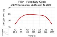
4.2 Audio Pulse-Width / Duty-Cycle and Sound-Spectrum (EW-REB 12-2020)
The objective sound spectrum consists of the lower-, mid- and high-pitch segment which slightly changes with volume as already described above. The spectrum is dependent on the pulse width. The diagrams below show the pitch dependent duty-cycle and pulse-ratio characteristics of the EW S/+ with added EW-REB 12-2020 extension board.
|  |
As can be seen, the duty-cycle of the mid pitch-range is typically 25%, corresponding to a pulse-ratio of 1:4. The lower-register shows a decline of the duty-cycle below 110Hz (A2), corresponding to a pulse-ratio up to 1:6. The upper-register shows a sharp decline of the duty-cycle above 880Hz (A5), corresponding to a pulse-ratio up to 1:6.
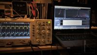
The following pictures show the audio pulses and resulting spectra at 440Hz (A4). For signal comparison, the EW audio-output signal (upper trace, yellow) and the speaker output as received by a microphone (lower trace, blue) are displayed at the oscilloscope screen-picture at the right.
 |  |
Additional diagrams can be found in the Measurements section.
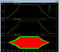
4.3 Audio Volume-Control Dynamic Extension (EW-REB 12-2020) (25.09.2022)
The basic volume control response of the EW S/+ does not apply a curve similar to a 'logarithmic potentiometer'. There is only a approximation included which provides a lower and a high linear level range. A smooth fade in at low volume is therefore hindered. The improved response curve of the EW-REB 12-2020 extension board realizes this 'logarithmic' characteristic (it is in fact a modified exponential curve). The dynamic is therefore greatly extended, especially at low volume levels.
A comparison of the original- and improved volume-response is shown in the simulation diagrams. The diagrams show the volume control-voltage V(ctrl-out-m/ctrl-out) at the LM13700 (U3C) output, at the extension board overshoot low-pass-filter (V-ctrl) and the resulting audio output signal of U3A V(af-out-m/af-out). The green curves represent the EW basic response, the red curves show the improved signals of the EW-REB 12-2020 extension board. As can be seen, the sharp control-voltage transitions are reduced. The adjustable overshoot improves the dynamic speed at rising- and falling volume, e.g. when playing staccato.
The schematic detail of the volume-control voltage amplifier is shown below. The improved dynamic curve results from a combined negative- and positive feedback to the control input of U3C pin16 via R110/R111/R138/C112 and to the negative input of U3C pin13 via D105 and R137, both sourced by impedance-converter Q101. The control voltage amplitude is adjustable by R111, to prevent instability of U3 when overdriven (excessive current draw), the peak volume can be set at R119. The volume cut-off level is adjusted by R140. It must be noted that all adjustments affect each other to some extend. The generated log. control voltage is additionally low-pass-filtered by the components arranged around Q102. This LPF circuit can be adjusted close to oscillation at R116, but usually only a slight over-/undershoot is musically usable. The values of the LPF may be adopted to the player’s needs.
") | ") |
4.4 EW Standard and EW+ Theremin Modification Circuit Descriptions (EW-REB 12-2020)
4.4.1 Front-Panel Circuit (EW-REB 12-2020) (25.09.2022)
The Front-Panel Circuit is somewhat simplified in regard to the first modification proposal as described above; it consists of the Power-Switch, the Indicator-LED, the Audio-Output Jack, the Mute-Switch and the Potentiometers for Volume, Pitch, Waveform and Brightness control.

The 14V AC voltage of the line wall wart, connected to jack AC-IN is routed to the Power-Switch S1 and back to the power-supply circuit (AC-OUT) via the front-panel connectors J9/109. The Audio-Output signal AUDIO-OUT is present at jack J1, which is supplied by the AF-Limiter VCA circuit via connectors J9/J109. The Volume-Potentiometer controls the amount of negative VOLUME control-voltage supplied to the AF-Limiter VCA circuit. The Pitch-Potentiometer controls the amount of negative pitch-tuning PITCH voltage, routed to the pitch-tuning circuit. The Waveform-Potentiometer controls the amount of negative WAVE voltage, routed to the AF-Limiter VCA circuit, determining the audio-signal pulse-width. The Brightness-Potentiometer’s output voltage BRIGHT is also routed to the AF-Limiter VCA circuit, determining the rise- and fall time of the limited audio-signal. The additional resistors R45 and R46 allow the BRIGHT control-voltage to become negative for extended control range when populated accordingly. It is possible to use the original assembly which gives a reduced adjustment range when not introducing R46 (denoted by R46 = NC) and leaving the lower connector of potentiometer P4 wired to ground (denoted by R45 = 0R).
The DC control-voltages VOLUME, PITCH, WAVE and BRIGHT as well as the +-12V supply voltage and ground are routed to the dedicated circuits via connectors J9 and J109. The Mute-Switch S2 (SPDT - Single Pole Double Throw: closes in the up or down position corresponding to On-On configuration) and the accompanying bi-color Indicator-LED D7 are connected to the extension board via J7 and J107. When in ‘Mute’ condition, +12V are supplied by the switch to the VCA and via D6 to the red partial LED. When ‘Play’ is selected, +12V is connected to the green partial LED and D6 is biased negative due to the voltage developed at the LED current set resistor R44. Because D6 is totally shut off, the VCA circuit’s mute input is disconnected, any current flow is prevented because the VCA level is well below the voltage at R44.
4.4.2 Volume Control RF-Circuit (EW-REB 12-2020)
")
The Volume-Control RF-Circuit consists of the Fixed Volume Oscillator (schematic denotation has to be changed), consisting of Q6, Q7 and the surrounding components with accompanying Volume Tuning Stage, controlled by the VOLUME voltage which is derived from the dedicated potentiometer located at the front-panel, build around Q8. The Volume Antenna Resonator/Detector unit is directly connected to the base of Q7. The value of C27 is reduced to 10nF for increasing detector signal rise-time and the cathode of detector diode D1 is connected to a tap of L7 for improved volume response. The detector circuit generates the volume-control voltage VDET, which can be overridden by the mute-voltage of Mute-Switch S2, located at the front-panel. VDET is directly routed to the Volume Control Amplifier.
4.4.3 Volume Control LF-Circuit (EW-REB 12-2020) (25.09.2022)
The Volume-Control LF-Circuit consists of the Volume Control Amplifier, the Volume Control Overshoot Low-Pass-Filter (LPF) and the AF-Limiter Voltage-Controlled-Amplifier (VCA). The schematic detail is already presented in ‘Audio Volume-Control Dynamic Extension (EW-REB 12-2020)’ above.
The Volume Control Amplifier U3C amplifies the VDET signal of the Volume-Detector in a non-linear (logarithmic) fashion; in the original circuit this is achieved by the feedback of D5 via R37 to the negative input of U3C.
The improved dynamic curve results from a combined negative- and positive feedback to the control input of U3C pin16 via R110/R111/R138/C112 and to the negative input of U3C pin13 via D105 and R137, both sourced by impedance-converter Q101. The control voltage amplitude is adjustable by R111, to prevent instability of U3 when overdriven (excessive current draw), the peak volume can be set at R119. The volume cut-off level is adjusted by R140. The generated 'log.' (actually a modified exponential curve) control voltage is additionally low-pass-filtered by the components arranged around Q102. This LPF circuit can be adjusted close to oscillation at R116, but usually only a slight over-/undershoot is musically usable.
In Leon Theremin’s original design of e.g. the Rockmore instrument, the over/undershoot is mainly defined by the bandwidth of the volume-control detector resonator-tank, which produces ringing at fast frequency changes, causing voltage variations of the resonator and thus the detector tube’s output. This resonator-tank is missing in Robert Moog’s design.
")
The AF-Limiter Voltage-Controlled-Amplifier (VCA) U3A/U3B is controlled by the VCA-CTRL signal provided by the Control Overshoot Low-Pass-Filter (LPF). The amplifier’s limiting behavior is defined by the additional control-voltages BRIGHT (connected to pin 2 via R27) and FORM (connected to pin 4 via R28).
In addition, a small amount of the VCA volume-control voltage (AUX) is added to the audio voltage via R101 at the AF-Detector (located at the extension board) providing a small offset, to slightly influence the sound-signal’s pulse-width at high volume levels – thus changing the sound-spectrum. This is comparable to the effect on the spectrum when whispering and screaming, which is easily distinguishable.
The audio-signal AUDIO to be amplified and limited is supplied to pin 3 by the AF-Detector stage. BRIGHT and FORM control-voltages are derived from the potentiometers located at the front-panel, which define the rise- and fall time (BRIGHT) and pulse-width (FORM) of the rectangular sound signal AUDIO-OUT produced by the VCA stage.
4.4.4 Pitch RF Circuit (EW-REB 12-2020) (25.09.2022)
The Pitch RF Circuit consists of the Variable Pitch Oscillator with connected Pitch Antenna Resonator, the Fixed Pitch Oscillator with accompanying Pitch Tuning Stage and the AF-Detector.
")
The Pitch Antenna Resonator unit is directly connected to the Q1 transistor’s collector of the Variable Pitch Oscillator. It uses transistor Q1, Q2 and the surrounding components. The Fixed Pitch Oscillator consists of Q3, Q4 and the surrounding components with accompanying Pitch Tuning Stage. This stage, build around transistors Q5 (tuning) and Q9 (stabilization) is controlled by the PITCH voltage which is derived from the dedicated potentiometer located at the front-panel.
The Fixed Pitch Oscillator’s partial oscillator tank coil L13 is moved to the position of C32. Therefore, the PCB tracks have to be cut at the C32 pads, L13 has to be unsoldered and resoldered at capacitor’s C32 position. At the bottom layer of the PCB, the two pads of C32 have to be connected to the L13 pads using rigid isolated wires, which have to be routed in some 5mm distance from the board.
")
Positioning L13 near L12 and the pitch antenna extension coils (L1 to L3), provides pitch antenna current dependent RF coupling between the pitch oscillators, thus providing the needed adjustable phase compensation. To reassemble the sound of the Rockmore instrument, a special sound spectrum pattern has to be generated. The spectrum has to change with pitch in a very special way. In addition, the sound has to vary slightly with volume. By bending the coils L13 and L12 changing their positions to each other as well as to the antenna coils L1 to L3, the optimal pulse width and pulse-pause ratio (duty-cycle) is defined. The ‘Brightness’ knob has to be set fully clockwise and the ‘Waveform’ knob has to be set to 15 o'clock or so. This leads to a rectangular sound signal with steep flanks and appropriate pulse-pause ratio, which removes the muffled original sound of the Etherwave.
The adjustment affects the pulse-pause-ratio as well as the rectangular pulse width, not for a single pitch but for the whole pitch range. This means that one has to try out an orientation and sweep the pitch range to check if the sound (pulse-pause-ratio and rectangular pulse width) changes according to the Rockmore sound. If the sound is not sufficient, the orientation has to be changed again. This procedure has to be repeated until every pitch sounds as desired.
At the AF-Detector, the RF signals RF-F (fixed) and RF-V (variable) are added via capacitors C6 and C2 and fed to the detector/mixer diode D104. The cathode of the diode is connected to the stabilized offset-voltage of approx. +0.7V, generated by D103 and R103. The offset shifts the detected audio signal to the appropriate DC level for limiting by the VCA stage. C104 shunts RF to ground. The amplitude of the detected audio-signal AUDIO can be adjusted by R125 for optimal limiter action of the VCA stage. The schematic detail is already presented in ‘Audio Volume-Control Dynamic Extension (EW-REB 12-2020)’ above.
4.4.5 EW+ Variant Front-Panel PCB Interconnection (EW-REB 12-2020)
The EW+ applies a front-panel PCB, which is additionally connected to the EW-REB 12-2020 extension board via J8, J108. The extension board is connected to the EW main-board via J1 and J101. Refer to ‘Audio Volume-Control Dynamic Extension (EW-REB 12-2020)’ above.
4.4.6 Power-Supply Circuit (EW-REB 12-2020)
")
The Power-Supply provides symmetrical +-12V DC voltages, stabilized by regulators U1 and U2. To reduce the current of U1 and U2 and thus the power-dissipation, especially at the EW+ variant, resistors R42 and R43 are introduced. This has only little effect on the residual hum; the circuit was already used by the GRUNDIG company in laboratory AF generators – of course it would be better to replace the 100mA regulators by types providing higher current and power-dissipation capability. The half-wave rectifier diodes D2 and D3 are bypassed by capacitors C32 and C33 to prevent the diodes from rectifying RF disturbances. Diodes D101 and D102 placed at the extension board, prohibit the supply-voltages from reversing during the power-on or -off process. The wall-wart coming with the Etherwave provides 14V Ac at 200mA. It is connected to the Power Jack J10 (DIN). The AC voltage is connected to ground and to the capacitor C31 which shortens RF disturbances introduced by the 14V AC line voltage (AC-IN) to ground. AC-IN is routed to the Power-Switch S1 which is located at the front-panel, and back (AC-OUT) to the rectifiers D2/D3 via the front-panel connectors J9/J109.
4.5 EW 12-2020 Extension Board Variants
4.5.1 Schematics of the EW 12-2020 Extension Board Variants
To realize different variants of the ‘EW-REB 12-2020’ extension-board, the board has to be populated with differing components. The according schematics of the ‘EW-REB 12-2020’ and ‘EW-SEB 12-2020’ variant are shown below. The ‘EW-SEB 12-2020’ represents a circuit close to the original EW S/+ theremin design (NC = not connected/populated).
 Theremin Rockmore Extension Board (EW-REB 12-2020) Schematic") |  Theremin Standard Extension Board (EW-SEB 12-2020) Schematic") | ||||||||
EW-REB_12-2020_SCH-BW_0v1.pdf EW(+) Theremin Rockmorizer Extension Board (EW-REB 12-2020) Schematic
|
EW-SEB_12-2020_SCH-BW_0v1.pdf EW(+) Theremin Standard Extension Board (EW-SEB 12-2020) Schematic
|
4.5.2 Prototypes of the EW 12-2020 Extension Board Variants

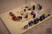
The realized prototypes of the two extension-board variants as well as the modified EW main boards are shown in the pictures below.
Prototype 1. of the EW-REB 12-2020 Rockmorizer Extension Board:
 |  |  |
 |  |  |
 | ") | ") |
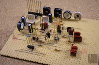
Prototype 2. of the EW-REB 12-2020 Rockmorizer Extension Board:
 |  | |
 |  |  |
 |  | ") |
Prototype 1. of the EW-SEB 12-2020 Standard Extension Board:
 |  |
 |  |
") |
4.6. Modified EWS/EW+ Main-Board (EW-REB 12-2020)


 |  |
 |  |
 |  |
 |  |
 |  Detail") |
 |  |
 |  |
 |  |
 |  |
 |  |
|  |
4.7. Modified EW+ Front-Panel with Mute-Switch & Indicator-LED (EW-REB 12-2020)
 | ") |
") | ") |
| ") |
 Detail") |
5. EW Standard and EW+ Theremin Modification (EW-REB 01-2021)
The ‘EW-REB 01-2021’ applies the form-factor and connections to the EW main-board already introduced in the ‘EW-REB 12-2020’ extension-board. The board uses the same circuit principles already described above. The picture on the left shows the EW-REB 01-2021 board of revision 0.1 .
 |  |
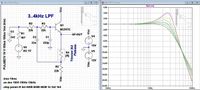
5.1 Active (AF) Detector Low-Pass-Filter
To improve the sound (pulse-width) in the high register, the passive audio frequency (AF) detector low-pass-filter (LPF) of the Etherwave Standard / Plus is replaced by an active filter, therefore C23 of the EW main-board has to be removed. The filter provides a sharp cut-off at frequencies above 4kHz and therefore reduces noise efficiently (harmonics are generated in the following VCA limiter stage at the EW main-board). It also introduces a slight increase in amplitude with rising audio frequency; the filter’s curve is adjustable as shown in the simulation picture below. Because of the adjustable resonance, the filter action is somewhat similar to the behavior (self resonance) of the vintage AF interstage transformers, as used by LT in his designs.
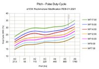
5.2 Pitch dependent Duty-Cycle and Pulse-Ratio Characteristics
The theremin sound-spectrum is dependent on the pulse width. The diagrams below show the pitch dependent duty-cycle and pulse-ratio characteristics of the EW S/+ with added EW-REB 01-2021 extension board at various settings of the WAVEFORM knob.
|  |
The sound file containing the corresponding EW-REB 01-2021 extension theremin sweep is provided here:
| EW-REB 01-2021 Pitch Sweep EW-REB 01-2021 Pitch Sweep REB-01-2021_SWEEP-MONO_07022021.mp3 (9.9MB) |
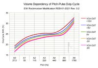
5.3 Volume dependent Pitch Duty-Cycle and Pulse-Ratio Characteristics
The next diagrams show the volume dependent duty-cycle and pulse-ratio characteristics of the EW S/+ with added EW-REB 01-2021 Rev. 0.2 extension board at various VCA-OUT control-voltages (at EW main-board J1 Pin2) which correspond to the audio output levels. The modified EW Theremin had been tuned as close as possible to the characteristic spectral distribution of the Rockmore sound-impression, which is mainly defined by the positioning of the pitch-oscillator coils L12 and L13 to each other. L13 was re-positioned as already described above in detail.
|  |
The sound file containing the corresponding EW-REB 01-2021 Rev. 0.2 extension theremin sweep is provided here:
| EW-REB 01-2021 0v2 Volume-Pitch Sweep EW-REB 01-2021 0v2 Volume-Pitch Sweep EW-REB-012021-REV02_SWEEP_S01.mp3 (8.63MB) |
EW-REB 01-2021 0v2 Volume-Pitch Sweep
| EW-REB-012021-REV02_SWEEP_S01.mp3 (8.63MB) |
5.4 Analog 440Hz ‘A4’ Pitch-Indicator
In addition, an analog 440Hz ‘A4’ pitch-indicator (pitch tuner), applying a bi-color LED, is added. The principle is quite similar to that used by LT (Leon Theremin) in the Rockmore / Rosen instruments. The LED is generally off, with rising pitch, the LED starts glowing red which intensifies when getting closer to 440Hz. Even closer to 440Hz, the color changes from red to orange and yellow, reaching bright green at exactly 440Hz. Above the exact frequency, the color changes in reverse order until the LED fades to off. When correctly adjusted, this pitch-indicator provides a sufficient means to the player for playing on key. The indicator allows to detect 220Hz ‘A3’ also; the brightness and color then only reaches orange to yellow.
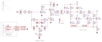
5.5 Schematics of the EW-REB 01-2021 Extension Board
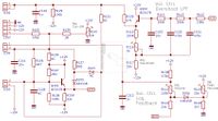
The schematics of the ‘EW-REB 01-2021’ variant are shown below (NC = not connected / populated); the positions of the connectors and adjusters are also shown.
 Schematic")
The schematic of the EW-REB 01-2021 Rev. 0.1 (shown on the right) contains an error which prevented the correct function of the volume dependent duty-cycle and pulse-ratio. Resistor R101 (4.7M), which determines the influence of the volume-control voltage to the duty-cycle (larger value = less influence), is connected to the output of the introduced Low-Pass-Filter (emitter of Q103). It had to be re-positioned to the input of the LPF to have sufficient effect. In addition, the value has been reduced to 3.3M ohms. This change is now included in the revised schematic (EW-REB 01-2021 Rev. 0.2) below and is shown in the pictures of the EW-REB 01-2021 Rev. 0.2 prototype board.
To improve the lower frequency response of the EW main-board somewhat, the value of C25 was raised from 1uF to 4.7uF which is not represented in the schematics yet.
 Schematic Page1") |  Schematic Page2") |
| EW-REB 01-2021 0v2 Schematic EW Standard / PLUS Theremin Rockmore-Extension Board (EW-REB 01-2021 0v2) Schematic EW-REB_01-2021_SCH-BW_0v2.pdf (158.17KB) |
EW Standard / PLUS Theremin Rockmore-Extension Board (EW-REB 01-2021 0v2) Schematic
| EW-REB_01-2021_SCH-BW_0v2.pdf (158.17KB) |
5.6 EW Standard and EW+ Theremin Modification Circuit Descriptions (EW-REB 01-2021)
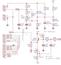
5.5.1 AF-Detector and Filter (EW-REB 01-2021)

At the AF-Detector, the RF signals RF-F (fixed) and RF-V (variable) are added via capacitors C6 and C2 of the EW main-board (not shown) and fed to the detector / mixer diode D104. The cathode of the diode is connected to the stabilized offset-voltage of approx. +1.4V, generated by D103 / D108 and R103. The offset shifts the detected audio signal to the appropriate DC level for limiting by the VCA stage located at the EW main-board. C104 shunts RF to ground. The amplitude of the detected audio AFD-signal can be adjusted by R125 for optimal limiter action (pulse-width) of the VCA stage. A low-pass filter (LPF) is used to improve the sound (pulse-width) in the high register. The passive audio filter of the Etherwave Standard / Plus is replaced; therefore C23 of the EW main-board has to be removed. The filter provides a sharp cut-off at frequencies above 4kHz and therefore reduces noise efficiently (harmonics are generated in the following VCA limiter stage at the EW main-board). It also introduces a slight increase in amplitude with rising audio frequency; the filter’s curve is adjustable by trimmer R123. Because of the adjustable resonance, the filter action is somewhat similar to the behavior (self resonance) of the vintage AF interstage transformers.
Resistor R101 provides a small offset-voltage (supplied by the volume-control circuit at Q101) to the input of the filter which serves to slightly change the duty-cycle of the pitch audio pulse with volume at the VCA limiter circuit. This makes loud and quietly playing more easily distinguishable, independent of the external connected amplifier volume-setting.
5.5.2 'Log.' (exponential) Audio Volume-Control (EW-REB 01-2021) (25.09.2022)
The improved volume-control response curve of the extension board realizes this 'logarithmic' (actually a modified exponential curve) characteristic as already described above. The dynamic is therefore greatly extended, especially at low volume levels. The schematic detail of the volume-control voltage amplifier is shown below.
The improved dynamic curve results from a combined negative- and positive feedback to the control input of U3C pin16 via R110/R111/R138/C112 and to the negative input of U3C pin13 via D105 and R137, both sourced by impedance-converter Q101. The control voltage amplitude is adjustable by R111, to prevent instability of U3 when overdriven (excessive current draw), the peak volume can be set at R119. The volume cut-off level is adjusted by R140. It must be noted that all adjustments affect each other to some extend. The generated log. control voltage is additionally low-pass-filtered by the components arranged around Q102. This LPF circuit can be adjusted close to oscillation at R116, but usually only a slight over-/undershoot is musically usable. The values of the LPF may be adopted to the player’s needs.
5.5.3 440Hz Pitch-Indicator (EW-REB 01-2021)
The simple 440Hz Pitch-Indicator circuit shown below applies a bi-color LED for displaying the 440Hz 'A4' pitch. As long as the pitch is far from 440Hz, the LED (D10) is dark. When the pitch gets near 440Hz, the LED lights red, even closer to 440Hz the LED color changes to yellow. When 440Hz is exactly tuned, the LED lights green. The brightness and colors of the LED change floating.
The bi-color LED D10 shall be mounted to the front-panel. It is connected to the PCB via three wires at J110. The raw audio-signal AF is supplied to the 440Hz filter input via C131 (providing AC coupling) and the large resistors R131 and R132 to provide loose coupling to the resonating filter. The value of R131 may be changed if the adjustment range of the trimmers is not sufficient. The filter applies a frequency selective circuit in double-T configuration. The center frequency is adjusted by means of trimmer R136, the peak amplitude and filter band-width is controlled by trimmer R138. The double-T components (creating a paralleled high- and low-pass filter), are placed in the feed-back path of the amplifier consisting of Q130 (amplification) and Q131 (impedance-converter). When R138 is advanced to much, oscillation of the filter will occur. The trimmers have to be adjusted alternately until the desired maximum 440Hz peak amplitude at the emitter of Q131 (filter output) is obtained; therefore a 440Hz pitch signal of sufficient amplitude has to be applied to the input AF at C131.
The indicator LED driver circuit applies an envelope detector, consisting of diodes D130, D131, capacitors C136, C137, resistor R140 and the trimmer R139 (for fine adjustment of the color display). As long as no AC signal is detected, the voltage level across C137 is low and Q132 to Q134 as well as the diodes D132 to D134 do not conduct. The bi-color LED, connected via current-limiting resistors R142/R144 to the collectors of Q132/Q133 stays dark. When the AC signal rises at the input, the detected negative voltage across C137 increases, thus Q132 starts conducting and the LED lights red. When the input signal further rises, D132 starts conducting as well as Q133, additionally enlightening the green LED section; thus the LED color changes from red to yellow. When the circuit is correctly adjusted by trimmer R139, a peak AC signal at 440Hz provides enough detected voltage to make D133 and Q134 conduct. The voltage-level at the collector of Q134 is fed back via D134 to the base of Q132, thus starting Q132 to shut-off when D134 conducts. The red LED section extinguishes and the indication color changes to green. The color changes are floating because of the transistors and diodes do not apply pure switching action. The values of the current setting resistors R142 and R144 have to be chosen according to the used bi-color LED, to set the desired color brightness characteristic.
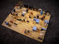
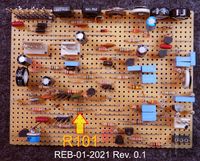
5.7 Prototype of the EW-REB 01-2021 Extension Board
The realized EW-REB 01-2021 prototype board of revision 0.1 is shown in the pictures below. The position of the resistor R101, which had to be changed due to incorrect functioning of the volume dependent pitch pulse duty-cycle, is marked in the last picture.
 |  |
 |  |
 | |
 |  |
|
The corrected EW-REB 01-2021 prototype board of revision 0.2 is shown in the next pictures; in addition, the changed position and value of R101 is marked.
 |  |
5.8. EW-REB 01-2021 Volume Response
Measurements at the ‘EW-REB 01-2021’ variant of the EW-S/+ Theremin extension-board have been performed to verify the volume response.
It must be emphasized, that in contrast to the linear pitch response of the theremin, the volume response has to be nonlinear (refer to ADSR envelope: Attack Decay Sustain Release) to make it easy for the player to produce a musical tone with smooth logarithmic (actually a modified exponential curve) fade-in (and fade-out) at very low volume with accompanying sharp rise (or fall) especially useful for staccato and crescendo playing. The traditions between the different steepness levels of the volume response curve have to be smooth to prevent unintended jumps in volume.
The velocity sensitivity of the Theremins as developed by LT (e.g. described in ‘EW-REB 01-2021’ chapter ‘Log. (modified exponential) Audio Volume-Control’ or in ‘General Functionality of the Rockmore- and Rosen Instruments according to Leon Theremin’s Design’ chapter ‘Volume Detector’) is not measured and examined in this chapter, even though it is already implemented in the described EW extension boards.
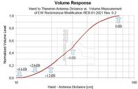
The diagrams below show the measurement data which was recorded using an early somewhat imprecise version of the Theremin Hand to Antenna Distance Indicator Device (THADID). The player’s hand was positioned above the volume-antenna, holding the THADID’s self retractable belt which was lead through the antenna-loop. The THADID device was placed on the ground below. The Theremin was set to produce a constant tone of approx. 440Hz.
Please note that all diagrams show identical data, only with various scaling and level of detail, to make it easier to examine the different regions of the theremin’s volume-response curve.
The diagram above shows the normalized linear scaled volume response at logarithmic hand to antenna distance scaling. In addition, markers have been added to indicate important volume levels in decibel (dB). The curve starts at zero, indicating minimum audio output (cut-off; approx. -84dB) of the Theremin with the hand positioned about 10 centimeters above the volume antenna. The volume rises slowly near cut-off, important for a soft fade in of the tone even when very quite. With further increasing hand to antenna distance, the volume rises sharply by 60dB (-84dB to -24dB) with is equal to a factor of 1000; this is important for playing staccato. Within 20 to 30 centimeters, corresponding to a hand distance change of 10 centimeters, the volume doubles (-12dB to -6dB). From 30 to 70 centimeters, the volume rise slows down, meaning another doubling within 40 centimeters.

The diagram above shows the low-level detail of the normalized linear scaled volume response at logarithmic hand to antenna distance scaling.

The diagram above shows the normalized linear scaled volume response at linear hand to antenna distance scaling.

The diagram above shows a detail of the normalized linear scaled volume response at linear hand to antenna distance scaling.

The diagram above shows the normalized logarithmic scaled volume response at logarithmic hand to antenna distance scaling. The curve starts below -80dB, indicating minimum audio output of the Theremin (cut-off), corresponding to maximum damping with the hand positioned about 10 centimeters above the volume antenna. The volume climbs slowly at first close to cut-off, but rises sharply with further increased hand to antenna distance. At a distance above 12 centimeters, the volume increase slows down with advanced hand distance.

The diagram above shows the low volume level detail of the normalized logarithmic scaled volume response at linear hand to antenna distance scaling.

The diagram above shows a detail of the normalized logarithmic scaled volume response at logarithmic hand to antenna distance scaling.
6. EW Standard and EW+ Theremin Modification (EW-REB 06-2021)
Because of the relatively complicated mechanical adjustment procedure of the coil L13 for generating the desired sound impression at the previously proposed EW S/+ modifications, a different approach (denoted as EW-REB 06-2021) will be described next. It also includes measures to improve pitch linearity.
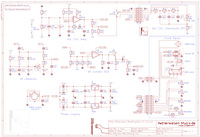
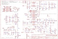
Schematics of the overall EW S/+ EW-REB 06-2021 circuit, excluding pitch indicatorare shown below.
Note: At revision 1.3 (2022-04-23), the pinning of U1 (78L12) was corrected as well as the designator of S2. The denotation 'Varaible Volume Oscillator' has to be changed to 'Fixed Volume Oscillator'.
 |  |
 |  |
| EW-Mod. 06-2021 1v3 EW S/+ Theremin Modification EW-REB 06-2021 Overall Schematic Rev. 1.3 EW-MOD_06-2021_SCH-BW_1v3.pdf (314.4KB) |
EW S/+ Theremin Modification EW-REB 06-2021 Overall Schematic Rev. 1.3
| EW-MOD_06-2021_SCH-BW_1v3.pdf (314.4KB) |
Schematics of the EW-REB 06-2021 board circuit:
 Schematic Page1") |  Schematic Page2") |
| EW-REB-06-2021 SCH-BW 0v3 EW S/+ Theremin Modification EW-REB 06-2021 Schematic Rev. 0.3 EW-REB_06-2021_SCH-BW_0v3.pdf (176.21KB) |
EW S/+ Theremin Modification EW-REB 06-2021 Schematic Rev. 0.3
| EW-REB_06-2021_SCH-BW_0v3.pdf (176.21KB) |
6.1 EW Standard and EW+ Theremin Modification Circuit Descriptions (EW-REB 06-2021)
6.1.1 Pitch RF Circuit (EW-REB 06-2021)
To improve the adjustment of the proper RF compensation, thus the pulse-width behavior and to avoid having to reposition L13 of the fixed pitch oscillator via long wires to a position near L12 / L3, a passive phase-shift circuit was developed.
The frequencies of the pitch oscillators had to be shifted to about 297kHz because of the large RF interference caused by digital aeronautical radio beacons at the author’s location in the middle of Germany. Especially after sunset, the strong LW radio beacons made it impossible to get a clean theremin audio signal.
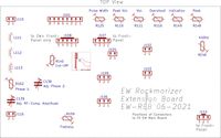
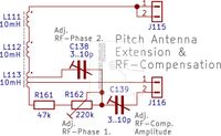
The RF phase-shift circuit is placed at the RF cold end of the pitch antenna resonator circuit, using introduced tappings of the partial antenna extension coil L3 (L113), as shown in the schematics. Because the circuit consists of two trimmer capacitors (C138 / C139), one resistor (R161) and one trimmer resistor (R162), the existing Rockmorizer Extension Board (REB) was enlarged to hold these components as well as the original pitch antenna extension coils L1 to L3, now denoted as L111 to L113. Additional connectors J15 / J115 and J16 / J116 are introduced to the main-board and the REB for interconnection of the RF signals.
")
As said before, it is beneficial to remove the three pitch extension coils from the EW main-board and mount them together with the other added components at the enlarged REB to keep RF connections as short as possible and to get a stable reliable wiring. In addition, when operating at frequencies close to 297kHz, the three existing coils can be used alone when placed in line as close as possible to enlarge the total inductance (the inductance of L3 / L113 is reduced when it is applied in the phase-shifter arrangement with the added tappings). When lower pitch oscillator frequencies shall be achieved, an appropriate additional extension coil of approx. 5mH has to be placed in series with the existing coils and the antenna to reach the desired sum inductance (not shown in the schematics).
")
To build the variable passive phase-shifter, L3 (L113) has to be equipped with tappings between the already mechanically separated parts of the winding. The coil then has four connections and serves as auto-transformer and phase-inverter. The first pin (seen from the RF cold side of the coil), is connected to the restive part (R161 / R162) of the variable phase-shifter arrangement. The second pin serves as the middle tapping of the phase-inverting transformer and is supplied by the large RF output signal of the variable pitch oscillator. The third pin is connected to the capacitive part of the variable phase-shifter and the fourth pin to the following series extension coil. C139, which is connected to the junction of the resistive / capacitive voltage divider (R161, R162, C138) forms an additional capacitive voltage divider in conjunction with the fixed pitch oscillator resonator (L6 / L13 / C5 ; RF-F). Mainly the amplitude of the phase-compensation RF signal can be adjusted via C139, while R162 and C138 basically affect the RF phase. The capacitive- as well as the resistive part of the phase-shifter arrangement have been made adjustable to provide a large alignment range.
The introduced phase-compensation circuit provides a comparable performance to the circuit applying the mechanically re-arranged coil L13 of the fixed pitch oscillator. Both arrangements supply the small RF compensation signal to the fixed pitch oscillator, which has to be dependent on the pitch antenna resonator current and thus pitch. The L13 coil arrangement acts sort of a variometer, providing an RF signal of variable phase and amplitude; the now introduced phase-shifter circuit does the same job without having to re-position the coil L13 during alignment.
The attentive reader may ask, why the simple compensation circuit which only consists of the small capacitor and the large resistor, which was presented firstly is not used any more, or at least not at the REB. The answer is simple; to achieve a ‘living’ Theremin sound (appropriate pulse-width / audio-spectrum modulation according to pitch), the antenna resonator current has to influence the compensation sufficiently. The simple R-C circuit introduced between the outputs of the pitch oscillators does not interact with the pitch antenna resonator current (the RF voltage amplitude of the pitch oscillators stays nearly constant during a pitch sweep); thus the compensation does not change sufficiently with pitch. Essential for the sound is the proper pulse-width which leads to the intended audio-spectrum that changes with pitch in the desired manner.
Note: It might be necessary to reverse the initial-polarity (initial-phase) of the auto transformer (L113) when the intended compensation / sound cannot be adjusted. This means that the tapping connections one and three of L113 have to be exchanged.
The diagrams of the EW-REB 06-2021 modification below show the component arrangement of the EW main-board and the extension board, including the positions of the alignment-trimmers.
 | |
6.1.2 Pitch Linearity Improvement (EW-REB 06-2021)
To improve the pitch linearity especially at the highest notes (hand very close to the pitch-antenna), the resonator circuit of the variable pitch-oscillator is changed as follows (refer to schematics): variable pitch-oscillator tank-capacitor C1 (3n3) is replaced by two capacitors which are connected in series. The junction of the formed capacitive voltage divider (virtual tap of L5 / L12) is now connected to the antenna resonator circuit. At the given schematics, the values of the capacitors C1 and C34 are optimized for operation around 297kHz. At the usual playing position, this circuit, combined with the RF compensation arrangement described above, gives optimal pitch linearity from the lowest to the highest notes. When the player’s body is positioned to close or far from the instrument, the linearity becomes more imprecise.
6.2 Pitch Linearity Measurements (EW-REB 06-2021)
")
The diagrams below show the results of the pitch linearity measurements using the dedicated Theremin Hand to Antenna Distance Indicator Device (THADID).
| THADID Sound Theremin Hand to Antenna Distance Indicator Device (THADID) Pitch Sweep Sound EW-REB-012021_THADID_PSweep_0v1.MP3 (1.4MB) |
Theremin Hand to Antenna Distance Indicator Device (THADID) Pitch Sweep Sound
| EW-REB-012021_THADID_PSweep_0v1.MP3 (1.4MB) |
6.2.1 Pitch Linearity Diagrams (EW-REB 06-2021)
") | ") |
") | ") |
") | ") |
") | |
6.2.2 Additional Pitch Linearity Diagrams (EW-REB 06-2021)
The diagrams below show the results of the pitch linearity improvement by connecting the antenna resonator circuit to the proposed capacitive divider circuit (4n7/6n8), replacing the single (3n3) parallel capacitor of the variable pitch oscillator’s coil as already described above. The measurements have been performed with grounded player (player’s leg and EW connected via 22n to PE) and without direct PE connection of the player for comparison. Three different distances of the player’s body to the modified EW Theremin instrument have been evaluated.
")
All measurements have been performed using the proposed Theremin Hand to Antenna Distance Indicator Device (THADID), which produces an audio beep signal every centimeter of (straight) hand movement. The beep can be recorded along with the pitch signal and evaluated after the pitch sweep has been carried out.
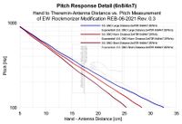
 |  |
The diagram on the left shows the pitch response for the three player positions of the proposed EW modification EW-REB 06-2021 (divider capacitors 4n7/6n8 at variable pitch oscillator) and grounded body. The curve for the player’s body at the normal distance (red) gives best pitch-linearity; the deviation wiggle from the linear line is small (lower range), especially when compared to the curve for the player’s body far away of the instrument (blue). The curve of the close distance measurement shows some non-linearity in the mid-range.
The diagram on the right shows the pitch response for the three player positions (grounded body) of the proposed EW modification with two additional 470 Ohms resistors added in series between the antenna extension coils (low Q) to lower the quality factor and broaden the antenna resonator resonance curve. The curve for the player’s body at the normal distance (red) gives best pitch-linearity; the deviation wiggle from the linear line is small (lower range), especially when compared to the curve for the player’s body far away of the instrument (blue). The curve of the close distance measurement shows some non-linearity in the mid-range.
Comparing the measurements indicates a slightly better pitch linearity for low Q antenna extension coils.
 |  |
The diagram on the left shows the pitch response for the three player positions of the proposed EW modification EW-REB 06-2021 (divider capacitors 4n7/6n8 at variable pitch oscillator) and body not directly grounded. The curve for the player’s body at the normal distance (red) gives best pitch-linearity; the deviation wiggle from the linear line is small (lower range), especially when compared to the curve for the player’s body far away of the instrument (blue). The curve of the close distance measurement shows some non-linearity in the mid-range.
The diagram on the right shows the pitch response for the three player positions and body not directly grounded of the proposed EW modification with two additional 470 Ohms resistors added in series between the antenna extension coils (low Q) to lower the quality factor and broaden the antenna resonator resonance curve. The curve for the player’s body at the normal distance (red) gives best pitch-linearity; the deviation wiggle from the linear line is small (lower range), especially when compared to the curve for the player’s body far away of the instrument (blue). The curve of the close distance measurement shows some non-linearity in the mid-range.
Comparing the measurements indicates a slightly better pitch linearity for low Q antenna extension coils.
In general, the pitch linearity for the grounded player is slightly better.
6.2.3 Short Distance Pitch Response (EW-REB 06-2021)
 |  |
The diagram on the left shows the pitch response of the grounded (red) vs. not directly grounded (blue) player’s body close to the instrument for the standard antenna extension coil configuration.
The diagram on the right shows the pitch response of the grounded (red) vs. not directly grounded (blue) player’s body close to the instrument for two 470 Ohms resistors added in series between the antenna extension coils (low Q) to lower the quality factor and broaden the antenna resonator resonance curve.
Comparing the measurements indicates a slightly better pitch linearity for low Q antenna extension coils. In general, the pitch linearity for the grounded player is slightly better.
6.2.4 Normal Distance Pitch Response (EW-REB 06-2021)
 |  |
The diagram on the left shows the pitch response of the grounded (red) vs. not directly grounded (blue) player’s body at normal distance to the instrument for the standard antenna extension coil configuration.
The diagram on the right shows the pitch response of the grounded (red) vs. not directly grounded (blue) player’s body at normal distance to the instrument for two 470 Ohms resistors added in series between the antenna extension coils (low Q) to lower the quality factor and broaden the antenna resonator resonance curve.
Comparing the measurements indicates a slightly better pitch linearity for low Q antenna extension coils. In general, the pitch linearity for the grounded player is slightly better.
6.2.5 Large Distance Pitch Response (EW-REB 06-2021)
 |  |
The diagram on the left shows the pitch response of the grounded (red) vs. not directly grounded (blue) player’s body far away from the instrument for the standard antenna extension coil configuration.
The diagram on the right shows the pitch response of the grounded (red) vs. not directly grounded (blue) player’s body far away from the instrument for two 470 Ohms resistors added in series between the antenna extension coils (low Q) to lower the quality factor and broaden the antenna resonator resonance curve.
Comparing the measurements indicates a slightly better pitch linearity for low Q antenna extension coils. In general, the pitch linearity for the grounded player is slightly better.

6.3 EW-REB 08-2021 Extension Board (25.09.2022)
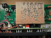
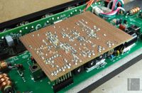
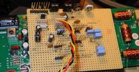
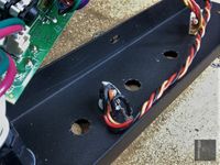
The realized EW-REB 08-2021 board of revision 1.0 is shown in the pictures below.
Currently, manufacturing of the PCB for testing and verifying the function is postponed.
The board represents the circuit of the already described EW-REB 06-2021, including the antenna extension coils and the passive phase-shift circuit to improve the adjustment of the proper RF compensation, thus the pulse-width behavior and to avoid having to reposition L13 of the fixed pitch oscillator via long wires to a position near L12 / L3.
 |  |  |
 |  | |
 |  |  |
 |  |  |
7. Preparation of Adjustment-Holes below the Oscillator-Coil-Cans at EW Main-Board
The oscillator coils are very sensitive and brittle, special care must be taken when milling the holes for adjustment from below (bottom of PCB). The holes have to be positioned at the center of the coil shield-can. It is not advisable to unsolder the coils because the risk of tearing apart the thin wires which are soldered to the pins inside the coil-can is very high due to the small PCB hole diameter. The ferrite core also should be stay in place, because it is likely to break when totally unscrewed. Due to the risk of damaging the coils, a high speed milling tool with appropriate diameter for the adjustment-tool is advised to be used and the penetration depth kept as low as possible (not affecting the coil body). There are ground tracks routed unnecessarily at the top of the PCB below the coil-cans, which have to be removed carefully after milling using pliers and scalpel. There have to remain no loose copper tracks. One bottom track below a coil-can has to be removed also; the connection has to be rewired manually.
Why this PCB (and housing) holes have never been included by Moog is a mystery; probably, the adjustment had to be kept as complicated as possible.
8. Modified EW Standard Front-Panel, Additional Controls, Power- and Audio Jacks


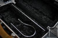
9. Modified Trumpet Traveling Case for EW Standard Theremin Use


